Neper Tessellation#
Overview#
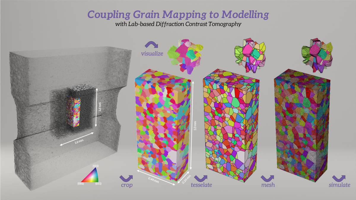
This tutorial describes how to convert a GrainMapper3D result *.h5 file to a *.tesr Neper input file, and how to run a Neper pipeline to tessellate, mesh, and visualize the grain structure.
Neper Basics#
Neper is a free / open source software package for polycrystal generation and meshing.
Tip
For more detailed help on Neper, consult the Neper documentation.
Note
Install Neper following the installation instructions. If you are using Windows, install Windows subsystem for Linux (WSL) first.
The following pipeline will uses these Neper modules:
The pipeline is a simplified version of the Neper tutorial:
The pipeline was tested with Neper version 4.10.2-2 running under Window Subsystem for Linux on Windows 11 Pro.
Data#
The data used for the pipeline is from the publication
Gille, M., Proudhon, H., Oddershede, J., Quey, R., & Morgeneyer, T. F. (2024). 3D strain heterogeneity and fracture studied by X-ray tomography and crystal plasticity in an aluminium alloy. International Journal of Plasticity, 183, 104146.
Further details and simulation results can be freely accessed at:
The data can be downloaded from
Data set summary:
6016 T4 aluminum alloy with an average grain size of 40 µm.
Wide dogbone shape to fulfill plane strain conditions during tensile deformation.
Original LabDCT map dimensions 0.5 \(\times\)1.6 \(\times\)1.6 mm\(^{3}\) (x,y,z) with a 4 µm voxel size.
Cropped volume 0.44 \(\times\) 0.24 \(\times\) 1.00 mm\(^{3}\) (x,y,z) – approximately six grains in thickness along the y-direction of near-zero strain in the plane strain condition (tensile z-axis).
The grain map comprises 1666 grains, all of which are at least 27 voxels, and no voids.
Step-by-Step#
Convert the Result File to tesr#
Download the GrainMapper3D Result File
sample_S_undeformed_6_grain_center_slice.h5into a new folder.Open a command prompt, navigate to the folder, and run the
pythonscript to a create the Neper input fileAl.tesr:>>> from gm3dh5.file import GM3DResultFileReader >>> result_file = "./sample_S_undeformed_6_grain_center_slice.h5" >>> tesr_file = "Al.tesr" >>> with GM3DResultFileReader(result_file) as f: >>> f.export(tesr_file)
Note
The remaining part will work with the created Neper input file
Al.tesr.You can also download the scripts used and run them from the command line directly
Clean the Grain Structure#
Clean the grain map in
Al.tesrby cropping surrounding empty volume and numbering the cells contiguously from 1 (command added for consistency since both have already been done in the provided example data), and output the cleaned grain map inAl-c.tesr:neper -T -loadtesr Al.tesr \ -transform autocrop,resetorigin,renumber,resetcellid \ -o Al-c
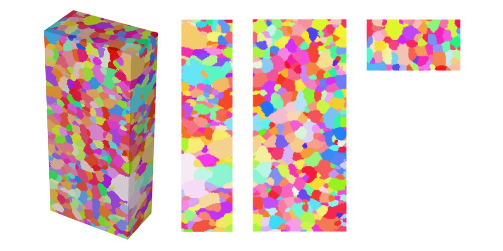
Visualize the cleaned volume in IPF color and store the 3D view as
Al-c.png, the views along the x-axis asAl-c-x.png, along the y-axis asAl-c-y.png, and along the z-axis asAl-c-z.png:neper -V Al-c.tesr -datavoxcol ori -datavoxcolscheme ipf \ -print Al-c \ -cameraprojection orthographic \ -cameracoo x+8:y:z -print Al-c-x \ -cameracoo x:y+8:z -print Al-c-y \ -cameracoo x:y:z+8 -print Al-c-z
Plot the 3D view of the central grains,
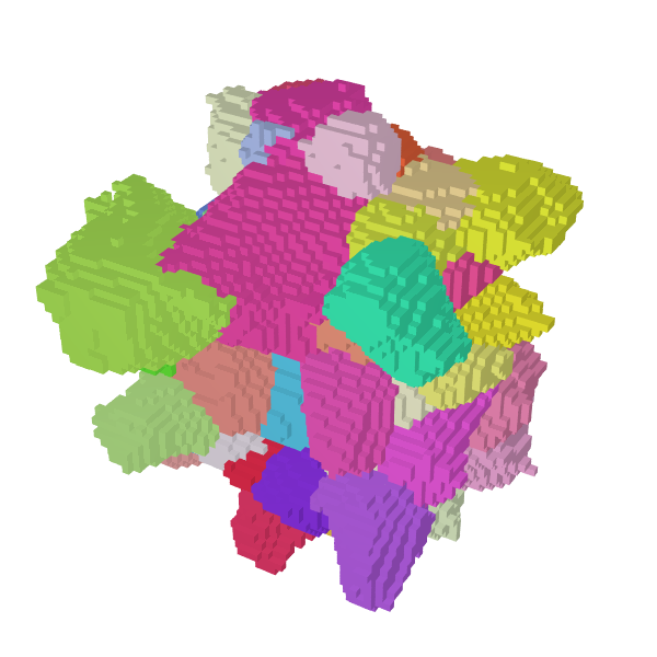
Al-c-center.png, as a zoomed square image to better see the details:neper -V Al-c.tesr -datavoxcol ori -datavoxcolscheme ipf \ -showcell "z>0.4&&z<0.6&&y>0.06&&y<0.18&&x>0.14&&x<0.3" \ -cameracoo x+length*vx/6:y+length*vy/6:z+length*vz/6 \ -imagesize 600:600 -print Al-c-center
Tip
If you open
sample_S_undeformed_6_grain_center_slice.h5in GrainMapper3D Viewer and apply the above bounding box it is possible to determine that in order to plot with the exact same grains as shown in , grain_ids: 666, 881, and 1008 must be removed and grain_ids: 704 and 1005 have to be added.Note
The Neper command to plot the above plot with and without selected grains is
neper -V Al-c.tesr -datavoxcol ori -datavoxcolscheme ipf \
         -showcell "(z>0.4&&z<0.6&&y>0.06&&y<0.18&&x>0.14&&x<0.3 \
         &&id!=666&&id!=881&&id!=1008)||(id==704)||(id==1005)" \
         -cameracoo x+length*vx/6:y+length*vy/6:z+length*vz/6 \
         -imagesize 600:600 -print Al-c-center
Determine the Tessellation Domain#
Define the domain, i.e., the actual external envelope, which the polycrystal fills perfectly. For the example structure this is easy, as it was cropped to be a box. Output as
domain.tesscontaining 1000 random grains.neper -T -n 1000 -domain "cube(0.44,0.24,1.00):translate(0,0,0)" \ -o domain
Adjust the
Al-c.tesrto thedomain.tessby growing the grains until they fill the entire tesr. Then intersect the tesr with the domain and finish by autocrop and renumber before writing the filled fileAl-cf.tesr:neper -T -loadtesr Al-c.tesr \ -transform "grow,tessinter(domain.tess),autocrop,renumber" \ -o Al-cf
Finally, remove potential “satellites” (voxels that would be disconnected from the rest of the grain) and write the satellite-free file
Al-cfs.tesr:neper -T -loadtesr Al-cf.tesr \ -transform "rmsat,grow,tessinter(domain.tess)" \ -o Al-cfs
The domain can be superimposed onto the tesr by first generating an image of the domain as a
domain.povfile:neper -V domain.tess -showcell 0 -showedge "domtype==1" \ -showface "domtype==2" \ -dataedgerad 0.0035 -datafacetrs 0.5 \ -imageformat pov:objects -print domain
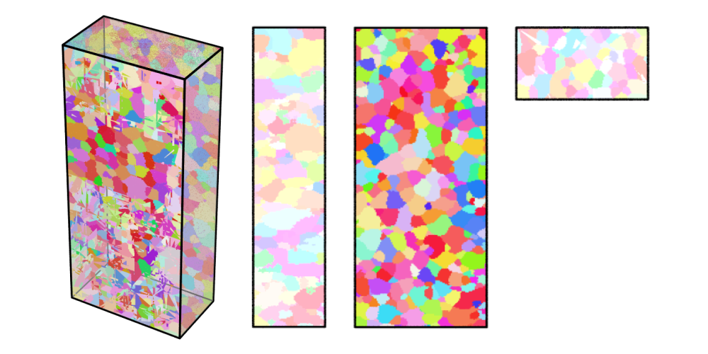
Visualize the cleaned, satellite-free volume with the domain boundaries in IPF color and store the 3D view as
Al-cfs.png, the views along the x-axis asAl-cfs-x.png, along the y-axis asAl-cfs-y.png, and along the z-axis asAl-cfs-z.png:neper -V Al-cfs.tesr -includepov domain.pov \ -datavoxcol ori -datavoxcolscheme ipf \ -print Al-cfs \ -cameraprojection orthographic \ -cameracoo x+8:y:z -print Al-cfs-x \ -cameracoo x:y+8:z -print Al-cfs-y \ -cameracoo x:y:z+8 -print Al-cfs-z
Tessellate the Grain Structure#
Generate a tessellation from the
Al-cfs.tesrusing the bounding box ofdomain.tessand output asAl.tess:neper -T -n from_morpho \ -domain "cube(0.44,0.24,1.00):translate(0,0,0)" \ -morpho "tesr:file(Al-cfs.tesr)" \ -morphooptiobj "tesr:pts(region=surf,res=10)" \ -ori from_morpho -crysym cubic -o Al
Note
The tesselation step to create
Al.tesstakes of the order an hour for the >186,000 iterations.Open the
Al.tessfile in a text editor and add thecrysym cubicinformation in the location indicated below to enable coloring the following visualizations by IPF:***tess **format 3.5 **general 3 standard **cell 1666 *crysym cubic *id
Regularize the tesselation by reducing the small edge length (threshold) to 0.25 times its default value and output the regularized tessellation as
Al-r.tess:neper -T -loadtess Al.tess -reg 1 -rsel 0.25 -o Al-r
Note
The regularization step to create
Al-r.tesschanges the grain affiliations of 527 voxels compared to the inputAl.tess.Visualize the regularized tessellation in IPF color and store the 3D view as
Al-tess.png:neper -V Al-r.tess -datacellcol ori -datacellcolscheme ipf \ -print Al-tess
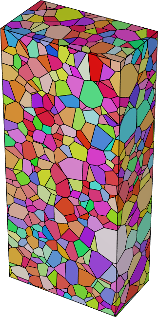
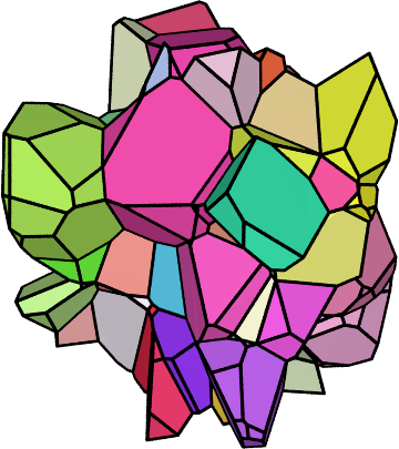
Finally, plot the 3D view of the central grains,
Al-tess-center.png, as a zoomed square image to better see the details:neper -V Al-r.tess -datacellcol ori -datacellcolscheme ipf \ -showcell "z>0.4&&z<0.6&&y>0.06&&y<0.18&&x>0.14&&x<0.3" \ -cameracoo x+length*vx/6:y+length*vy/6:z+length*vz/6 \ -imagesize 600:600 -print Al-tess-center
Mesh the Tessellated Grain Structure#
Mesh the regularized tessellation,
Al-r.tess, and output to the default filenameAl-r.msh:neper -M Al-r.tess -rcl 0.5 -pl 8
Note
The meshing step to create
Al-r.meshtakes of the order 20 min.Visualize the mesh in IPF color and store the 3D view as
Al-mesh.png:neper -V Al-r.tess,Al-r.msh -showelt1d all \ -dataelset3dcol ori -dataelset3dcolscheme ipf \ -print Al-mesh
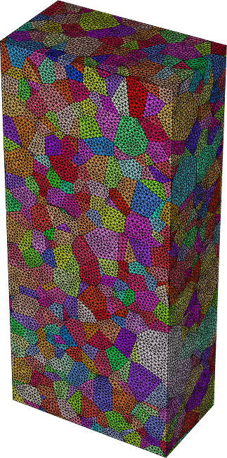
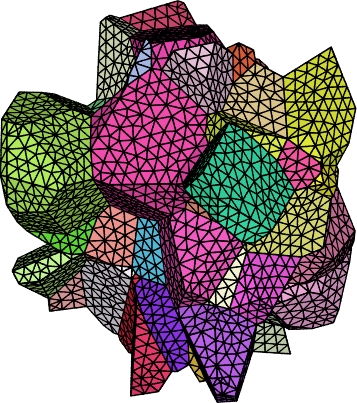
Finally, plot the 3D view of the meshed central grains,
Al-mesh-center.png, as a zoomed square image to better see the details:neper -V Al-r.tess,Al-r.msh \ -showelset "z>0.4&&z<0.6&&y>0.06&&y<0.18&&x>0.14&&x<0.3" \ -showelt1d elt3d_shown \ -dataelset3dcol ori -dataelset3dcolscheme ipf \ -cameracoo x+length*vx/6:y+length*vy/6:z+length*vz/6 \ -imagesize 600:600 -print Al-mesh-center
